

Understanding your 3D printer’s limitations and the way these might affect the design and manufacturing of 3D printed elements will information you alongside the trail of manufacturing the best high quality merchandise.
Most customers of Fused Filament Fabrication (FFF) 3D printing expertise perceive that the decision on completed prints / elements is usually 100 microns or higher with some producers claiming printer decision of fifty microns.

Determine 1: Printing the Dimension Accuracy Mannequin
Decision is just one standards that skilled customers apply to find out the standard and worth of a 3D printer. In an annual competitors, Make Journal convenes a Digital Fabrication Shootout to evaluate the standard of machines at totally different value factors. Make’s testing standards is helpful for any proprietor or person of a 3D printer to find out the tolerances and high quality of their tools.
The standards and corresponding Check Print Fashions run the gamut from precision / accuracy and end to machine capabilities. There are 9 main components to think about through the testing of your 3D printer. These components are listed under and expanded upon with causal particulars and strategies of mitigation in an effort to produce the best high quality fashions and elements.
Dimensional Accuracy
Dimensional accuracy is nothing greater than demonstrating that your completed print / half possesses the identical dimensions of the unique half or design. That is usually problematic when the bottom or backside of a component is subsequent to the mattress. Warmth and curing might trigger warping and sometimes the preliminary base layer of a print is programmed with extrusion charges in extra of 100% to make sure that the half adheres to the mattress (See Figures 1 and a couple of). This ends in a wider preliminary layer and with ensuing dimensions higher than designed. Many customers try and mitigate this concern by using a raft base earlier than printing the primary layer of the particular half.
One also needs to take into account the implications of infill on the finished half. With 100% infill, the quantity of fabric when cured might overlap or lengthen the completed half past the specified dimensions. There may be additionally a possibility for warping through the curing course of. From expertise, a MatterControl infill setting at 85% works greatest for a high quality most infill.
Lastly, remember that the layer top set for the z-axis has a direct correlation to dimensional accuracy within the z-direction. Typically instances, the most effective technique to make sure dimensional accuracy is to print at a layer top of 100 microns and to set the perimeter speeds between 15 – 30 mm/s.

Determine 2: Instance of Over Extrusion and Warping
Horizontal Floor End
Subsequent to warping and stringing, floor end is the attribute most seen by the tip person. Floor end is commonly materials particular with PLA having a notoriously poor floor end. One technique to enhance the horizontal floor end is to decrease the highest / backside layer extrusion speeds to inside 15 – 30 mm/s. It could additionally assist to extend the depend of high / backside layers to 5 to make sure a clean end (See Determine 3). Submit processing could be an efficient software to bettering floor finishes. Supplies reminiscent of ABS are simply sanded and sealed and a shiny end could also be produced by an Acetone Vapor Smoothing course of. Simply do not forget that most 3D printed elements as a part of an finish product are sometimes publish processed.

Determine 3: Discover the Roughness of the End As a result of Layer Peak Floor Angle
Vertical Floor End
High quality vertical floor finishes are a direct results of layer top, nozzle diameter and perimeter extrusion speeds. Rising the variety of perimeter layers would most likely not have an effect on the floor end within the z-direction, however printer extrusion velocity and layer top ought to be adjusted for the most effective end. Additionally, consider the kind of supply materials that you’re utilizing when adjusting the extrusion velocity and hold your layer heights between 100 – 200 microns. As all the time, publish processing will improve the floor end of a high quality half or finish product (See Figures 4 – 6).

Determine 4: Discover That the End on Sharp Angles is Not as Clean as on Curves

Determine 5: Curved Surfaces are Often Smoother

Determine 6: Angled and Curved Surfaces
Overhangs
Overhangs are the bane of designers and engineers when creating fashions for 3D printing. The prevailing steerage is both to place the half so there are not any overhangs or to offer precise or 3D printed helps within the z-direction as soon as printing begins. When 3D printing with overhangs, the most effective steerage to recollect the 45 diploma rule. Most printers can print overhangs as much as 45 levels with little points, however angles as much as 70 levels could also be achieved if in case you have your 3D printer dialed in (See Determine 7). Moreover a layer top discount and a decrease extrusion velocity might help in printing angles higher than 45 levels. One other technique of mitigating the overhang problem is to design in chamfers or fillets on the strong mannequin. This may help the printer in adjusting for the overhang hole. In the long run, trial and error whereas adjusting layer top and extrusion velocity will reveal the utmost overhang angle that your printer will have the ability to efficiently mitigate.
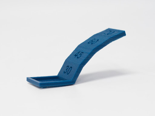
Determine 7: Discover the Roughness of the End at 60-Plus Diploma Angles
Retraction Efficiency
Stringing is a visual and publish processing nightmare. It’s most frequently obvious when trying to print a couple of mannequin or half concurrently or when a mannequin or half has giant gaps or unfavourable house. Stringing is a direct results of the retraction size and velocity settings for a selected print (See Determine 8). Nonetheless, don’t be dismayed. A useful reference information on retraction and how one can mitigate stringing could also be discovered at Retraction: Simply say “No” to Oozing.
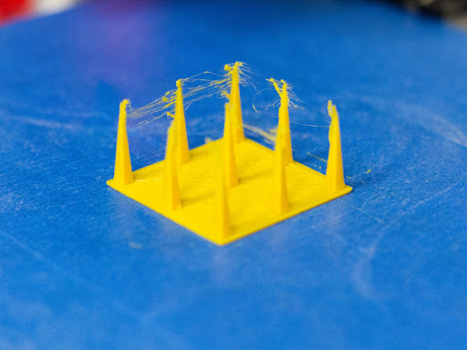
Determine 8: Instance of Stringing As a result of Retraction
Bridging
Bridges are printed flat sections that cross open spans within the mannequin. Printing bridges is one thing of an “artwork” and lots of fans make movies of distances that they have been in a position to span on their printers in a typical “are you able to beat that” bravado. With most bridges whereas printing at common speeds, a span of 50mm is widespread. Nonetheless, some printers can do even longer spans and the size of the span might also be depending on the kind of materials used. When bridging, hold the extruder velocity between 20 – 30 mm/s. The default setting for bridges in MatterControl is 20 mm/s (See Determine 9). Simply do not forget that the sooner the velocity, the higher the possibilities are for filament sags. Trial and error is the modus operandi for this course of as you slowly synch your machine with the optimum supplies and speeds.
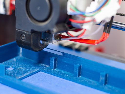
Determine 9: Instance of Bridging
Damaging House Tolerance
One other thorn within the sides of designers and engineers is the unfavourable house tolerance problem. This actually comes into play when trying to hitch prints or elements collectively into one meeting. Damaging house dimensions are materials particular and are affected by curing and floor end. Many of those points could also be mitigated by design, however trial and error together with your particular machine will normally give you a transparent path ahead (See Figures 10 and 11). For extra info on this topic, be happy to check with the reference article MatterHackers Lab: Design 3D Printed Assemblies.
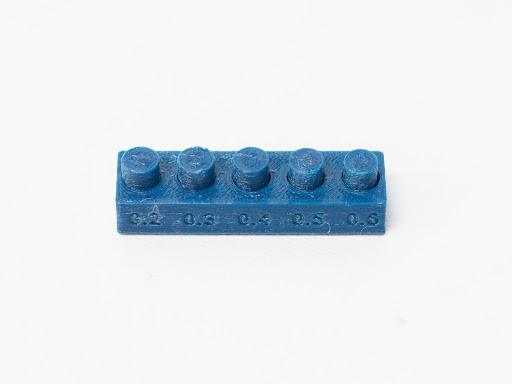
Determine 10: Damaging House Check Mannequin With a Damaging House of .2 and .3mm
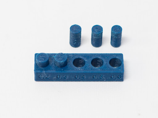
Determine 11: Discover That the Two Pins Printed Have been Not Capable of be Eliminated
Z-Wobble
Z-wobble is completely a mechanical problem and is most definitely attributable to out-of-tolerance mechanical elements and / or improper machine calibration (See Determine 12). It’s prevalent with Cartesian sort printers, particularly these with twin z-axis ball screws. Cantilever stiffness additionally performs into the wobble phenomena as usually Cartesian printers have loads of “play” within the printer carriage itself. To be able to mitigate this problem, ensure that your extruder and printer carriage are moderately stiff and that the carriage traverses alongside the cantilever in a stage method. In different phrases, ensure that your machine is stage and calibrated accurately. Some elements over time will put on, so ensure that the screws / ball screws and bearings are maintained, lubricated and in good situation. If there was some put on, chances are you’ll wish to change the elements. Should you hear any grinding or sounds of friction, make sure you revisit part and mattress leveling processes. The reference article How one can Calibrate Your Extruder will lead you thru the calibration course of for extrusion.
The appearance of Delta printers solves or at the least mitigates the z-wobble problem. Z-wobble is virtually eradicated on a Delta printer as a result of much less weight on the extruder housing and in using three towers from which to droop the extruder. Most Delta printers make the most of the Bowden resolution which retains the extruder motor off of the carriage. This elegant resolution has improved upon most of the points related to an ordinary Cartesian printer.
")
Determine 12: Instance of Z-Wobble (Picture courtesy of Danie Grobbelaar)
Assist Materials
When you’ve got been 3D printing for various years, you’ll know and perceive the challenges of including and using assist materials. Older slicing options have been infamous for printing assist materials that was virtually unimaginable to take away, with some helps really adhering and melting to the half itself. In the present day’s controllers present a assist resolution that’s a lot simpler to take away and sometimes locations “air gaps” between the precise half and the supplies forming the helps. For a base setting in MatterControl, make the most of the ten% infill setting of line patterns at 2.5mm intervals in producing helps. Additionally, embrace a raft (the article Printing with a Raft supplies background info) with the helps to make sure that the assist materials adheres to the print mattress. An “air hole” of .3mm is the default, however chances are you’ll wish to alter this setting on an as wanted foundation. Be happy to extend the infill settings and reduce the intervals must you want extra assist all through the mannequin. The aim of helps is to offer sufficient materials so that each one aspects of the mannequin could also be printed coupled with ease of removing of the assist materials as soon as the print is completed. For these with twin extruder printers, chances are you’ll wish to make the most of assist filament to incorporate HIPS and / or PVA in one of many two extruders whereas printing.
In abstract, the standard of your 3D printed elements hinges simply as a lot on understanding your machine’s tolerances and capabilities because it does on print mattress leveling, machine part leveling, machine calibration and the design and positioning of the mannequin / half for printing. Printing the Check Print Fashions in your machine with totally different supplies and settings will be sure that you understand your machine’s capabilities and the place your tolerances could also be adjusted. This like all good issues in life will take time, so step again and benefit from the journey. You’re a grasp creator and your expertise and capabilities will produce distinctive elements and merchandise for all to take pleasure in.